
(Diese Seite ist nur in Englisch verfügbar.)
...shows some information about the Fairlight CMI, my restauration of a CMI II, the development environment, some tools, and small programs I wrote for it. This includes a connection to a PC, and utilities for data exchange.
This page was started on 2009-06-04. It was originally made to give a little Thank you :-) and some hopefully interesting information back to JBE & PN :-) :-) who greatly helped me out with a working copy of the CMI II system disk. Some updates were added on 2010-07-28, and a link from outside was finally installed, to describe a successful 8" to 3.5" floppy drives mod.
Much of the work reported here was done between 2009-01-20 and 2009-03-04. I can still spend only a little time for its publication; to provide an initial, small, un-polished, selection from my ressources. So this page is definitely work in progress :-)
Disclaimer: As long as not otherwise noted, all material shown here, including software, screenshots and photos, was produced by myself; thus I'm holding the respective copyright. Trademarks may be mentioned on this page without notice, they are the property of their respective owners.
Please leave the photos on this page and don't pull them out of context. You're welcome to link directly onto this page though.
Exclusion of liability: This information is provided for private studying and educational purposes only. You may require specialized knowledge and tools before you can put the information on this page to any good use. I do not provide any express or implied warranty with regard to the usability, functionality, or safety, or anything else, of the software or any other information provided on this page.
If you like and want to support my work, any contribution is highly welcome. Commercial users, please suggest an appropriate remuneration.
Your feedback, your suggestions and your questions are welcome, too; and I hope this page will prove interesting and useful for you.
For simplicity, I start by putting everything onto a single page. This list provides orientation:
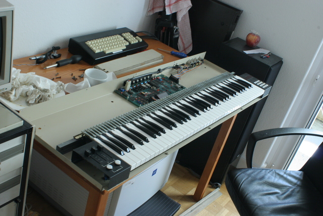
The Fairlight CMI (Computer Musical Instrument) was one of the first sampling synthesizers, but also a completely integrated synthesizer workstation.
As far as I can see at the moment, this might be the coarse line of development of the underlying hardware:
Because much has already been written about it: please look up more information in the external links section of this page.
From Peter Vogel's audio archive:
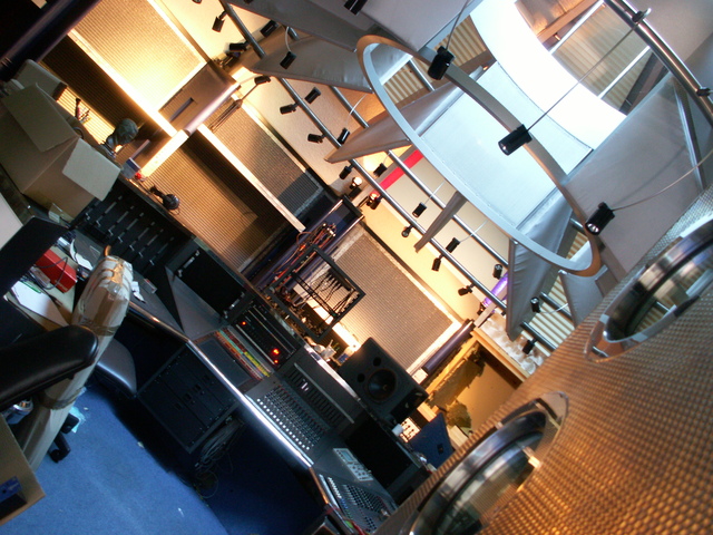
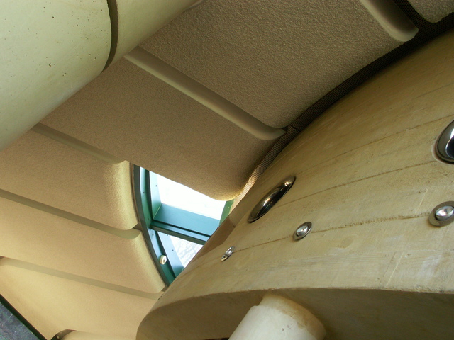
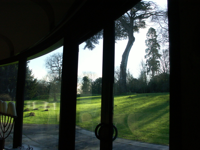
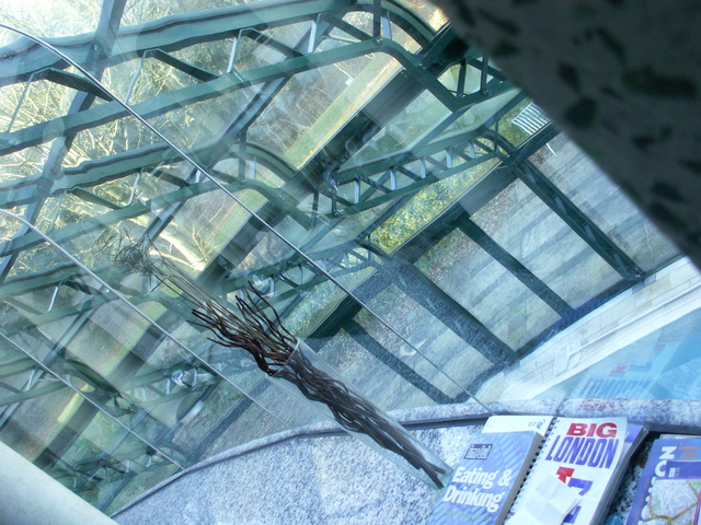
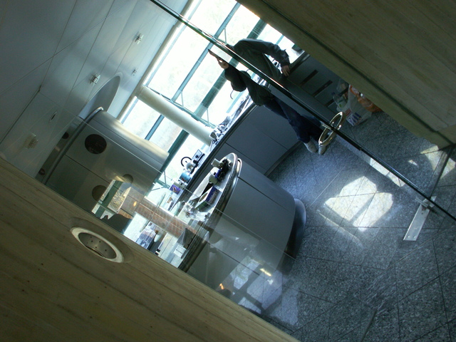
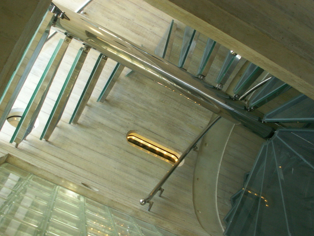
My system was previously owned by Vince Clarke, and I had to pick it up at studio 37B. No, I didn't meet him in person - he had already moved. But I met his former, very specially architectured house: "Ammonite", or "The round house" as a local was calling it.
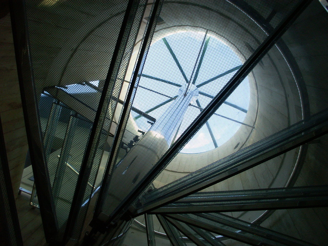
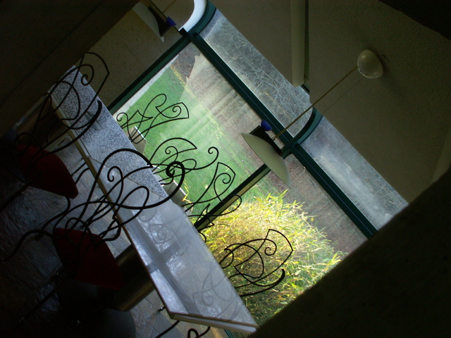
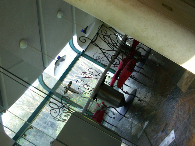
I think it is one of the more impressive examples of architecture I've ever seen - the design had a truly distinctive theme, made me personally feel comfortable at once, and then made me smile at one example after another for little ideas, specialties, humour and variation, and obviously visible love of and care for details:

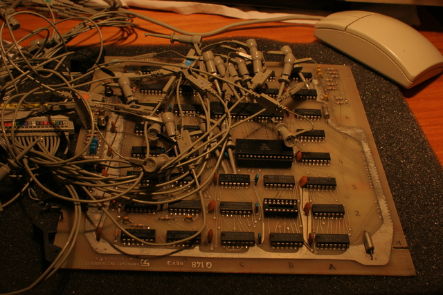
The instrument had been advertised as having suffered from a flood in the basement of the studio, with unknown working condition:
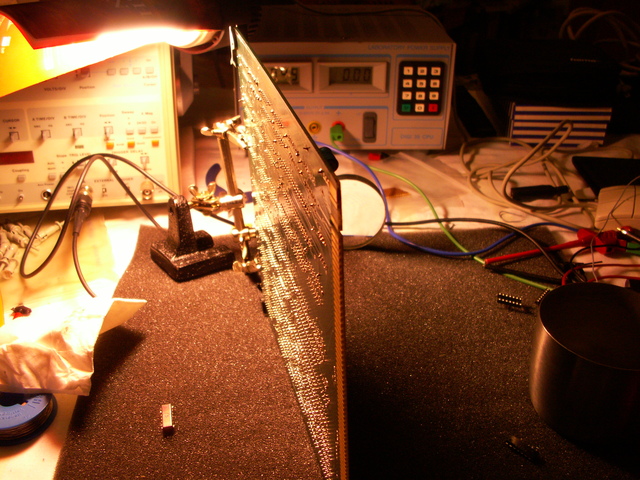
At the beginning I knew little about which parts might be defective. So I tested the boards individually in a static state, then in minimal system environments. Quite early, I bridged serial input of the cpu control card to the serial output, so I was able to type with the alpha keyboard onto the musical keyboard display - showing that both were ok, and the cables as well.
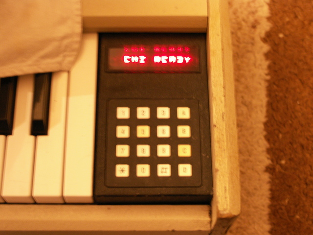
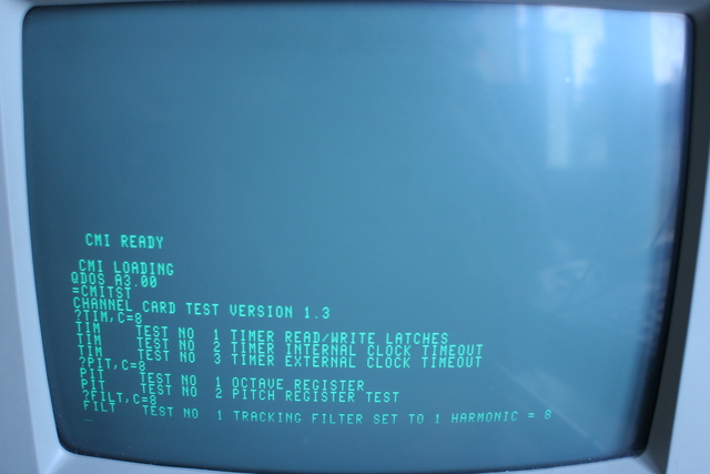
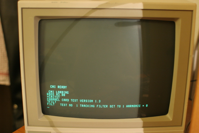
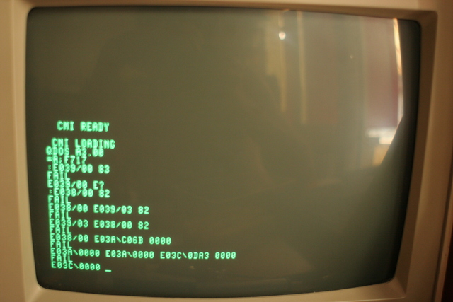
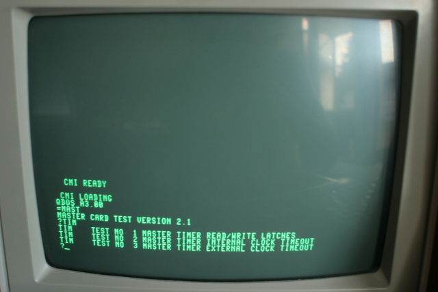
Isolating one error after another, and replacing each defective IC, I first made the CPU card work within a few hours. Which sufficed to see "CMI READY" on the keyboard (and myself jumping happily at half past three in the morning). Alas, the thing would still not boot from disk - and a very small number of power cycles later, the message would not appear any more either. :-(
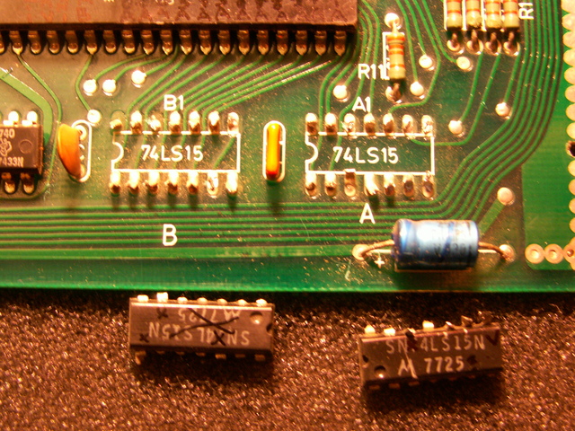
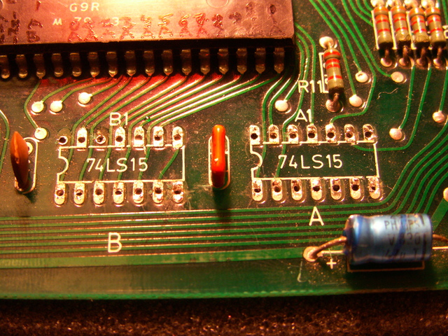
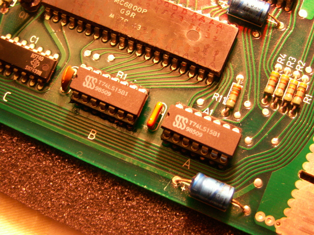
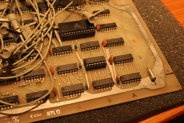
IIRC, the first three ICs to be replaced were all Motorola 74LS15N on the dual CPU board (and at least one more of this type needed replacement on another board).


Some months, and a partial move of equipment fell in between before I was able to look at the machine again. One serial port controller on the CPU control card had to be replaced, and "CMI READY" reappeared. Hope restored :-) Then I went for the graphics controller - some video output appeared - and then for video memory. Now I could use the ROM console debugger - but had to assemble code on a PC and type it in by hand. As I didn't know the calling addresses of video ROM routines, my programs would use the musical keyboard display by directly controlling the serial port. At that stage, disk boot attempts resulted in the video screen being visibly filled with data - and that occured in multiple passes. So I guessed that disk reading would probably work, but a DMA counter would probably run away forever. I wrote some software to monitor the floppy controller status, deciphered a number of essential ROM routines, and programmed the software to back up first a track, and then a complete image of my only system disk, reading from disk via polled i/o and writing the results to the serial port. This time with proper text output to the video screen. The floppy disk controller, including its discretely built DMA register logic, was fixed. Consequently, as far as I remember, the system managed a number of boot loader runs from the original disk - and would display the message that it couldn't find CMI.SY - but this result became more and more difficult to obtain, and a visible ring on track 0, where the magnetic coating was obviously missing on the system disk, was the most plausible explanation for that.
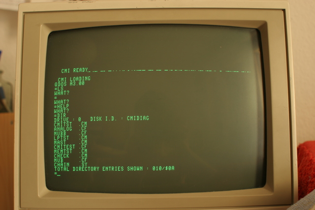
Several months later, I had been given a working set of system disks - including a diagnostic disk, as well as three releases (one current, two historic) of the CMI II operating system. The machine booted the diagnostics first, which just displayed a few more pixels than required, and even could copy individual (!) files between disks - but was still unable to run a complete disk backup. And when trying to boot the proper system disk, that would just load patterns onto the screen and end with the "WHAT?" prompt.

Video memory access control required a PIA to be replaced - have you ever wondered why these things are much more readily available and much cheaper to get by plane from Hongkong than by bicycle from the absolutely international :-) electronics shop downtown - or even from an electronics distributor just half an hour away?
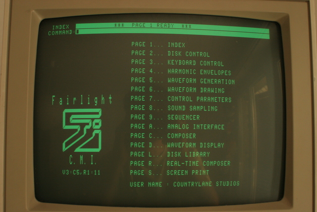
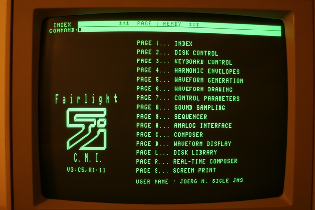
Anyway, with the PIA replaced, the machine would finally show the CMI II Index Page. Jippieh!
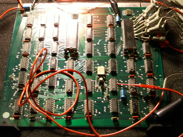
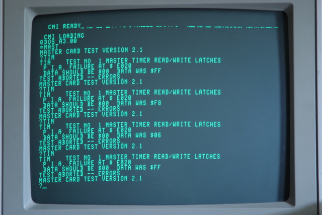
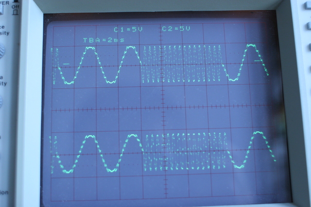
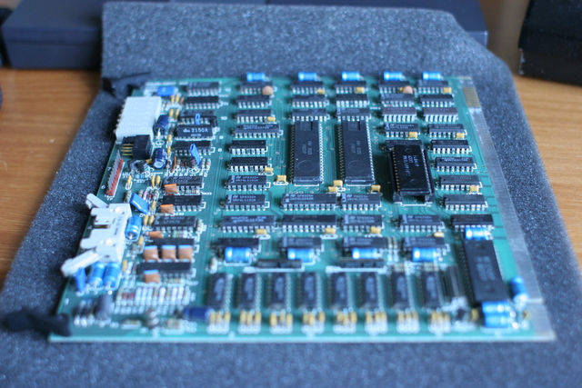
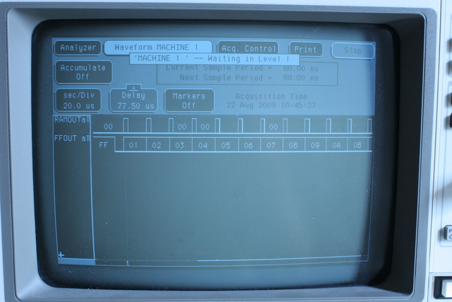
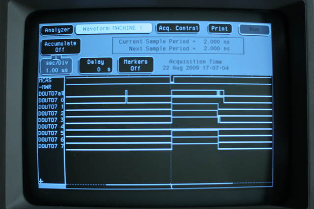
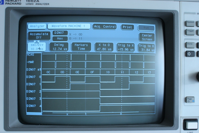
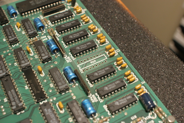
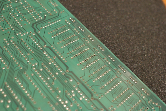
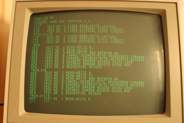
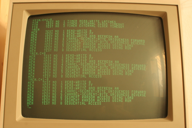
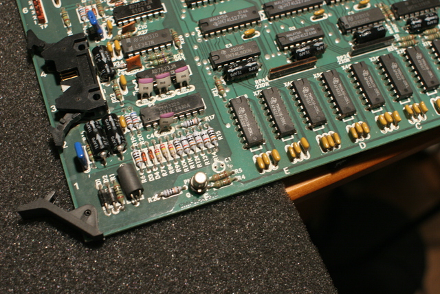
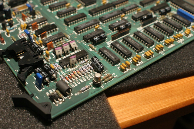
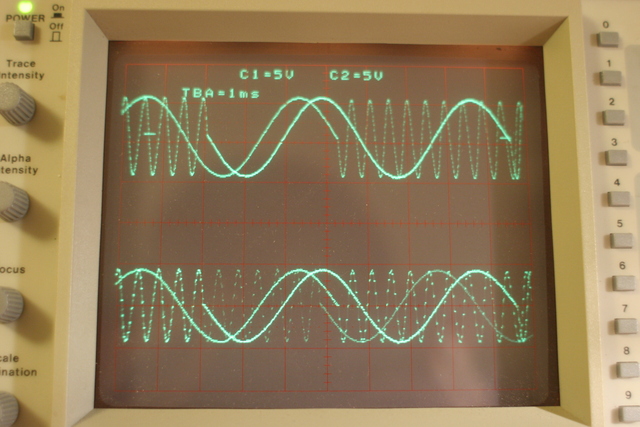
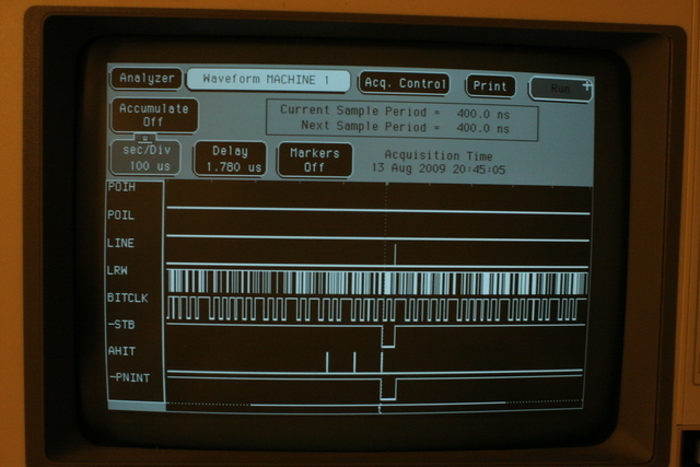
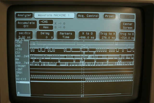
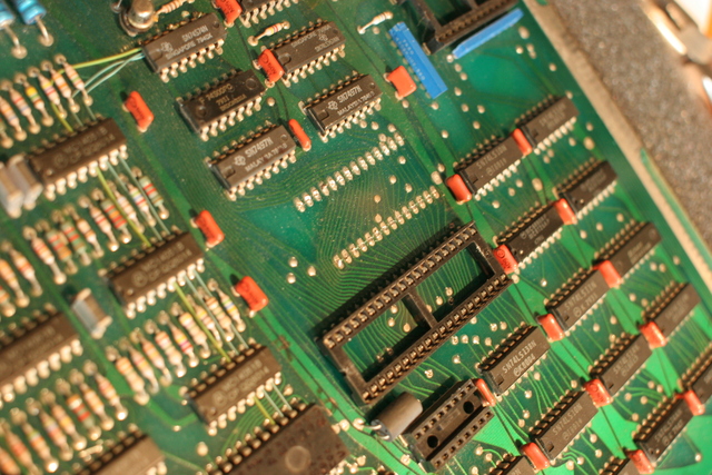
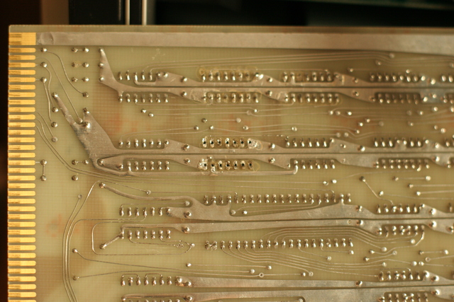
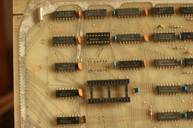
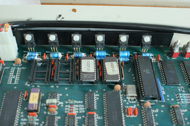
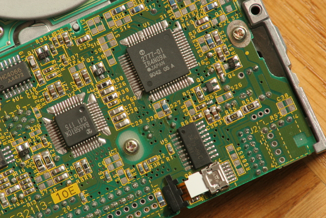
One channel card produced outstanding noise, from one of its eight RAM ICs being defective, always returning the same bit state. The following photos show the localization of the bit error in the voice card by observation of a sinus wave, by CMI diagnostic software memory testing, and via logic analyzer (the card's memory content should count straight upwards but falls back to 20 instead of going to 30 after 2F etc.) Besides, it should be possible to reduce power consumption and CMI II induced global warming by 40W at least, by replacing all memory chips with more modern ones...
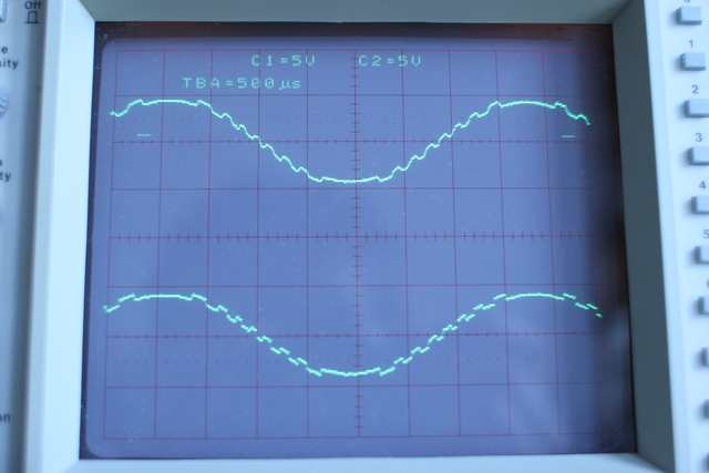

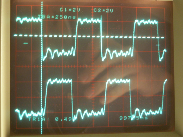
Another channel card had low output - from a dead coupling capacitor in the analog signal path. The scope shot might possibly show the post repair conditions directly after the DAC, and after the replaced output coupling capacitor filter:
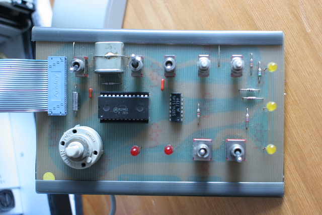
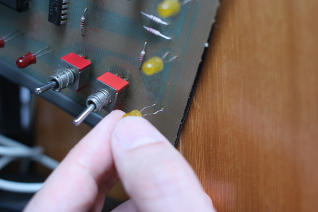
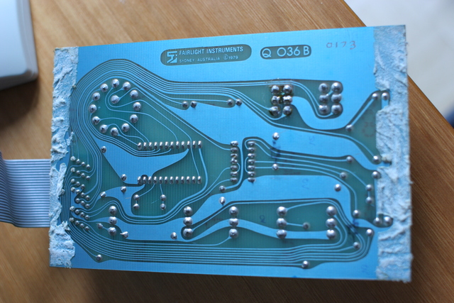
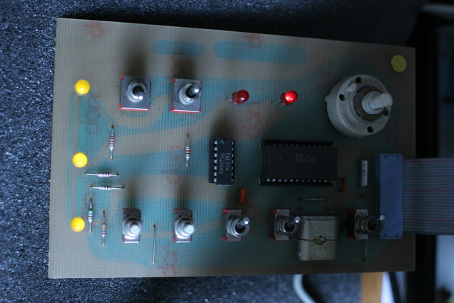
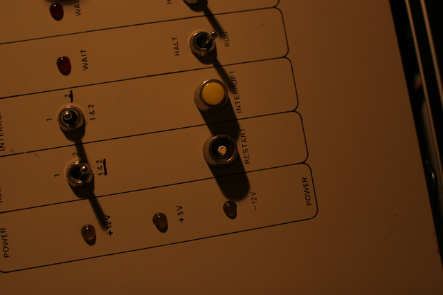
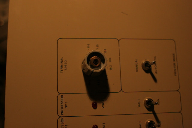
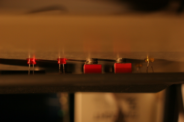
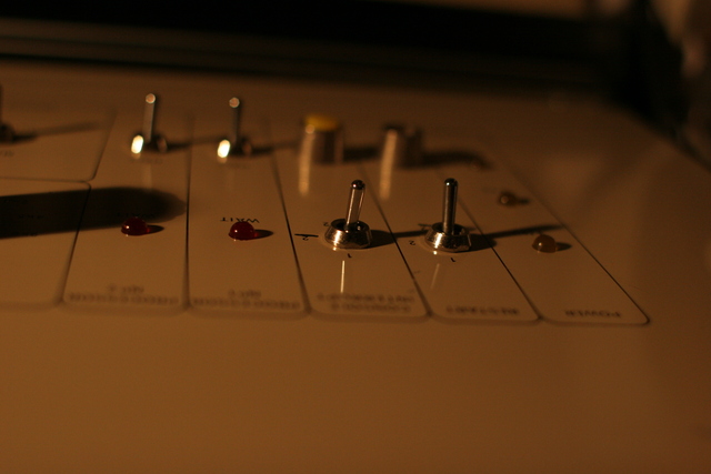
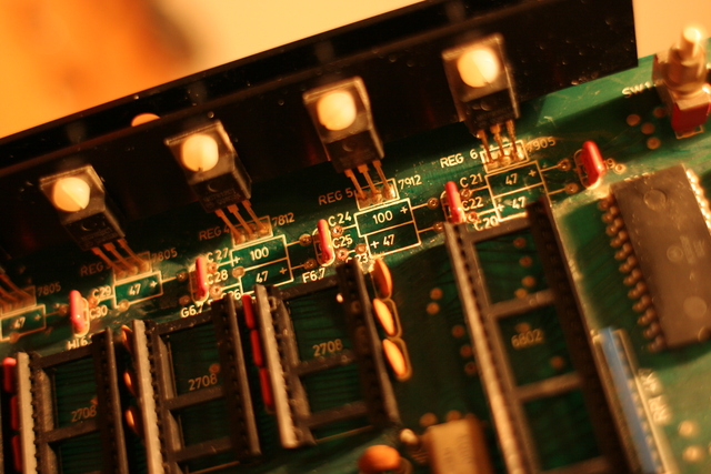
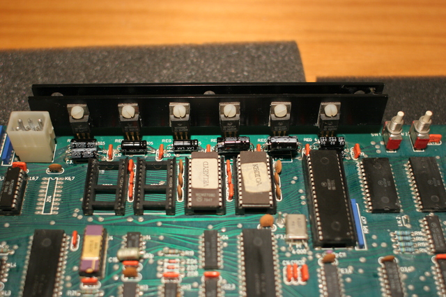
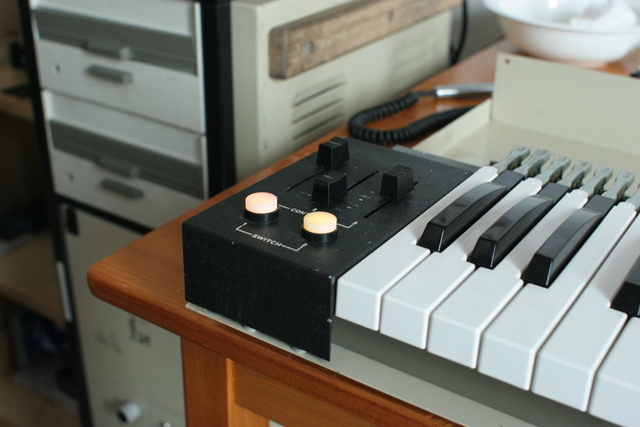
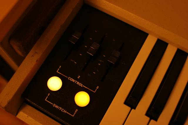
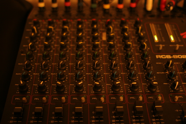
In the front panel, I replaced both red LEDs (one had gone dark, the other to keep their colours matching), reseated a yellow one whose foot had broken directly above the PCB. I also replaced the IC used to control them because one of the voltage lights had gone out even though the power supply would correctly provide it. The fotos document the relation of knobs, caps and fixating screws in case someone should need to remove their front panel from the machine:
The lightpen position readout would render positions with too low resolution, i.e. multiple columns or lines on the screen would render the same readout - so you could move the pointer over the screen (in a jumpy fashion) to see that the lightpen itself worked, but it was not able to select all menu items, control fields, or especially to draw curves or the like. One IC was replaced first, which improved the situation but did not completely do the job (lightpen continued below):
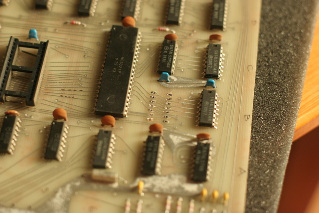
While most of the machine did work by now, the sequencers, would still not run - until a programmable timer IC was replaced in the musical section master card. One channel card had a socketed one I used for (successful) testing - and another plane from Hongkong, once again superior to the European market, would bring the final resident:
The lightpen card also required replacement of two of the 74LS295 counter registers. This IC, although a standard 74xx type, was not listed with suppliers anymore and I was lucky to come across some of these at my former default electronics part store in the city where I had studied once. Afterwards, the lightpen worked perfectly again:
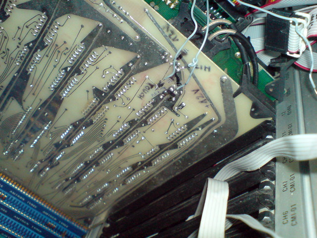
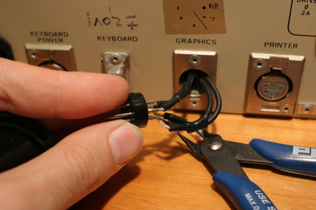
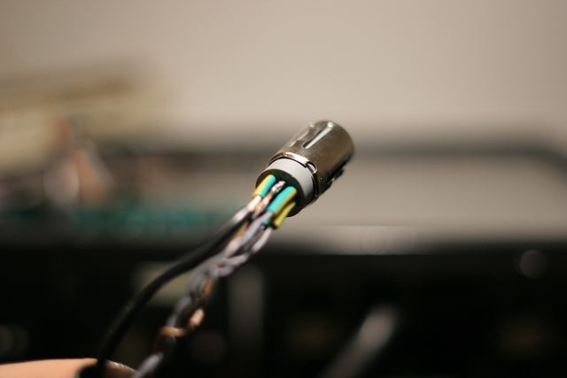
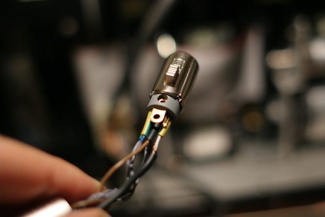
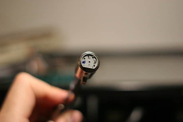
As the original monitor was missing, I had long ago added IC socket pins to receive a direct cable link from the card to the lightpen. The four IC socket pins shown here are all that is required to connect the lightpen directly to this card for testing purposes. One of them provides a +5V power source. The original graphics connector at the back of the system does not include that, as the original Fairlight video monitor carries the original receptacle and also includes a power supply. Consequently, the CMI has wires to route the TOUCH, HIT and GND signals to its backside connector, I only added another wire for +5V (see further below):
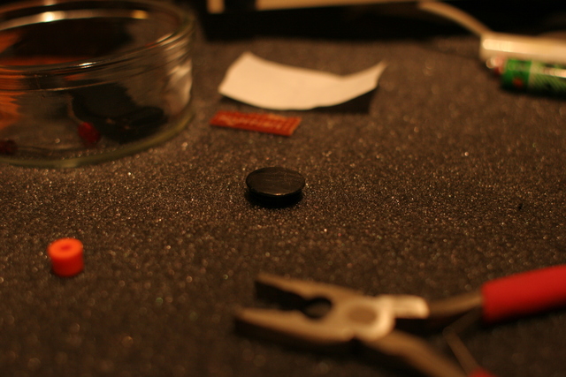
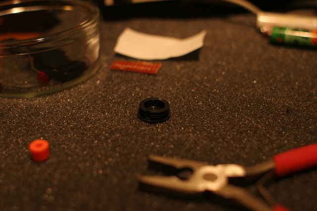
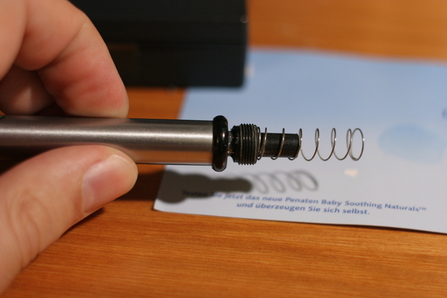
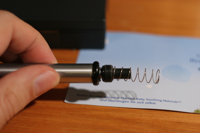
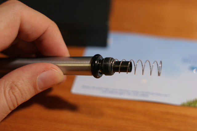
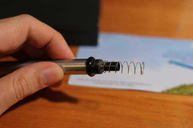
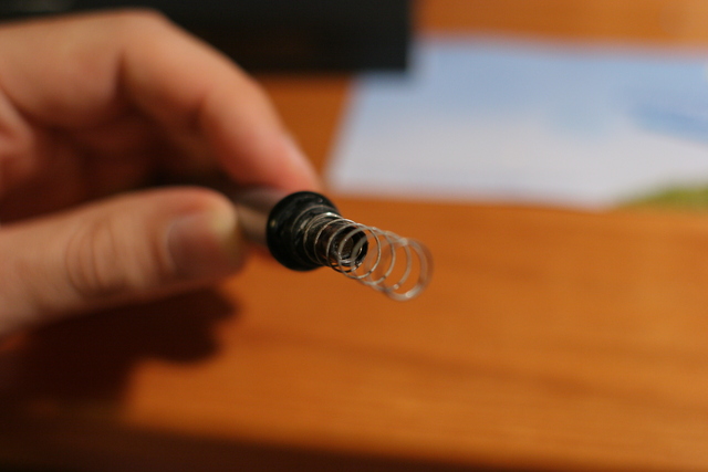
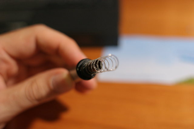
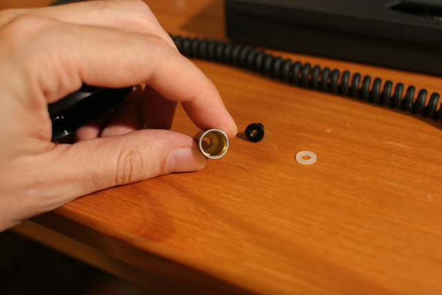
The interior of the lightpen tip contained a broken plastic part (the black portion, between the bulging ring and the screw thread) which could be mended again. Fotos from multiple points of view especially to reveal the interiors to all who consider opening such a pen, including the connecting wire visible in the second image, actually being part of the spring which is a conducting element here. The (probably steel) wire is crossing the chasm between the broken plastic parts. It may be in danger of being bent or torn when trying to move the spring or the lower plastic part, or to damage that itself:

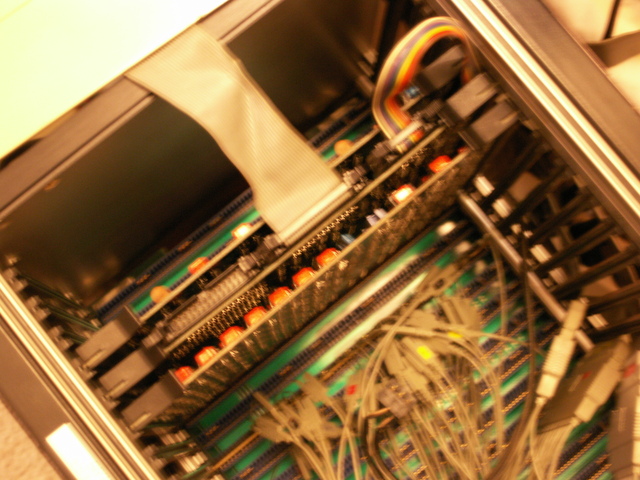
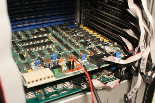
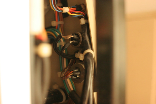
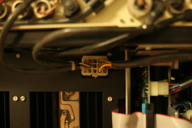
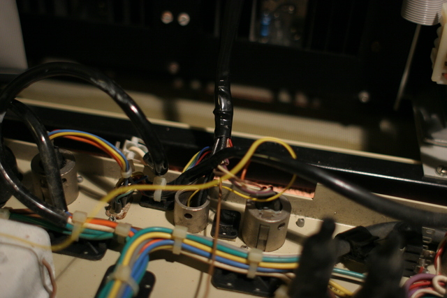
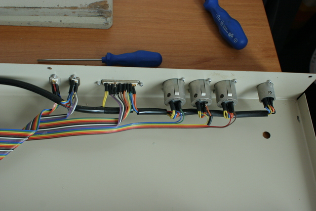
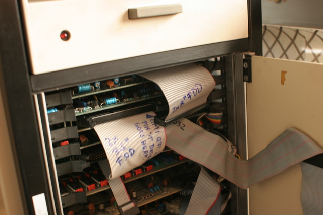
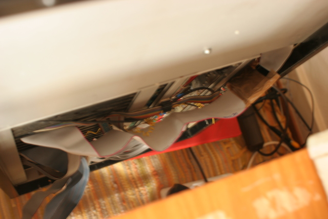
Later, I replaced the original graphics connector by an XLR connector with additional pins in order to provide a +5V power supply on the same connector (which would originally have been generated in the monitor). The following images document floppy drive and other cabling in the interior of the rear of the machine, which is much less accessible than anything behind the front door:
Luckily, an XLR connector interior part can be removed and replaced by another (having more pins) without any need to remove the outer part (which is fixed to the machine case with rivets rather than screws). The flexible yellow wire is the newly added one to providing +5V to the lightpen. The firm brown wire has been temporarily attached to the yellow one, only to pull it through the plastic hose around the respective group of cables:
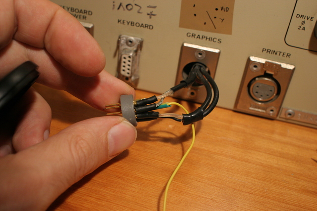

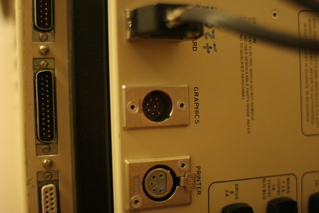
Into the newly upgraded socket fits this XLR cable: It brings the video wires to the video screen (a normal RCA male plug suits most 15kHz B/W or PAL video monitors), and the lightpen wires (now including power) to the lightpen. While I have identified the original lightpen connector and got a sample, I haven't made a proper flexible adapter cable, nor built an adatper box to carry that connector so far. Instead I directly inserted the four wires into the lighpen connector and fixed the connection with tape. Meant as ad-hoc solution but has been stable ever since:
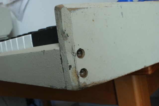
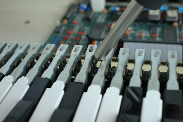
On the musical keyboard, not all of the covers over the front screws were still in place. The screws were rusty and the case finish very worn on one side - possibly from contact with water (similar to the wooden bars below the CMI main case - but really, I would not want to guess [...]). - For some keys, the rear portion needed to be minimally lifted or lowered in its hinge which could be done by carefully using a screwdriver as a lever (upwards), or carefully applying pressure with the fingers (downwards). Afterwards, all keys were better vertically aligned, moved easily and equally, and no key would knock against the top cover of the keyboard case when bouncing back up (where a felt strip might be added, if ever I should review the keyboard case):

The following images show the cabling of the external connectors. I made a relatively simple XLR to 6.35mm stereo adaptor to use a (nowadays) normal sustain pedal with the Fairlight keyboard (not shown; and vaguely remembering my trying it out, the CMI uses a different concept for sustain and consequently it might be more helpful to use a volume pedal (with a potentiometer) routed to the decay parameter...).

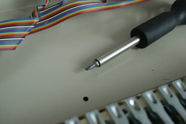
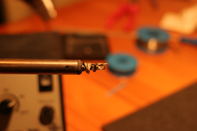
I also replaced all of the (probably) power supply related caps which had leaked and dried out so much that some virtually dissolved while desoldering: the capacitor body would separate from its connecting wire still soldered to the board very easily, while more of that dried, white powdery substance would fall onto the board. Removing the remaining solder from the PCB holes turned out to be quite difficult - the usual measures would not work - I finally added a thin hot wire tip to the soldering iron and freed the holes with that:
Then I replaced a burned out keyboard light by an LED. Initially, I just bent the LED and its resistor into a suitable form that would fit into the lamp socket. But it would not remain securely put, resulting in an eccentric illumination. One attempt to more properly reseat it with the machine running caused a short destroying the lamp driver - this may have been the only active part killed by rather unwise "therapeutic" action in all of the endeavour. I soldered the LED and the resistor into the metal connectors removed from the original lamp. The next images show an ad-hoc replacement for the driver IC made from individual parts; unnecessarily (as learned later), the diodes try to reproduce its OR-ing function as well. That hasn't worked out as desired; the lamps are now always on. The LED is too yellowish anyway and the driver will sometimes be replaced - but apart from the cosmetic ones, there's probably no functional drawback associated with the current state:


At that point, metronome click and sampling were the last missing items - this turned out to be a non-standard cabling problem (see below). After correcting that, everything was functional.
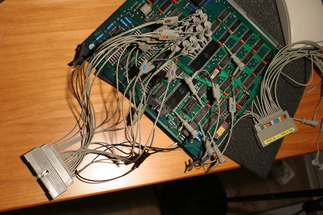
All in all, some 20 faulty ICs and a few other components on almost every type of board in the system were first reliably identified and then carefully replaced. For defects that could not be located by measuring individual IC functionality, hypotheses had to be generated from observations and thinking, and afterwards to be confirmed. It was not feasible to just monitor "all of the system" - due to its complicated, segmented and interleaved bus design which prohibited the moving of cards to arbitrary places - leaving hardly any space to access them with the logic analyzer. Neither would it have been a low risk endeavour (nor an affordable one, both money- and time-wise) to just replace all electronic parts in the system. Nor did I have replacement cards to identify defective ones by swapping them in and out again.
As of 2010-07-28, the system has been brought back to a completely working condition for quite some time.
Two remaining cards I haven't looked at so far are:
Detailed information on symptoms, hypotheses, diagnostic results and repairs may be made available later on. Whenever I may take the time...
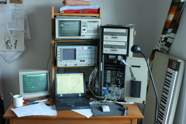
As soon as the main CPU cards worked, I wanted to be able to program the system in order to aid the further debugging.
My first software development environment was put together by trying out 6800, 6809 and FLEX related ressources retrieved several years earlier from the WWW:
The first small programs were compiled on the PC and the hex code manually entered into the monitor program available in the CMI ROM.
In the beginning, I had no working video display on the CMI. So my first programs sent any output to the display of the musical keyboard through the respective system port.
These programs were helpful as I could test the system from its own CPU's points of view, thereby reducing the necessity for complicated and much more time consuming logic analyzer setups, and later, even giving me the ability to use a few of the included ROM-routines for my debugging and reviving efforts.
Details and documentation on the assembler as well as configuration files I use for very streamlined assembly, and on the symbols understood by the musical keyboard display, as well as example programs, may be added later.
In the meantime, Hermann Seib has provided an 6800/6809 assembler a09 and disassembler f9dasm which run under both DOS and Linux.
Of course, some original software development tools do exist, which run natively on the CMI. But when I originally needed a development environment, I did not have the necessary ancient software. I had a defective video output and a defective disk controller instead - no way to use the original tools, even if I had had them available back then.
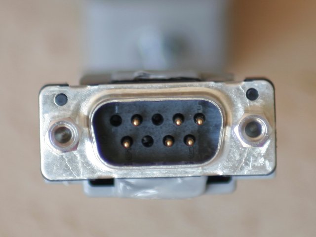
The CMI II uses a bidirectional RS-232 interface to communicate with both keyboards. I connected a PC to it.
A special cable is required for this purpose:
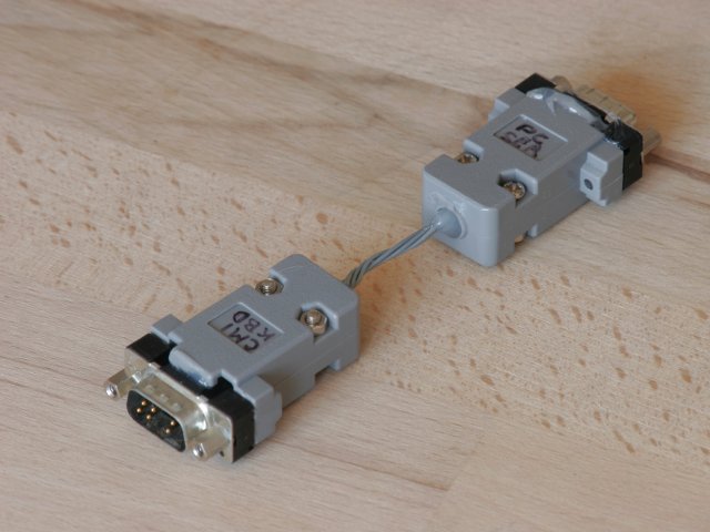
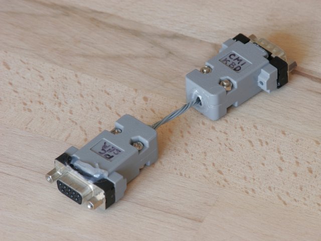
Here are solutions for various tasks:
For a start, I provide statically compiled or assembled binaries of my programs.
I may (quite probably) add the source code later on, but I need some more time before I will do that - e.g. to review the available license types etc.
Until then, I reserve all reasonably and possibly reservable rights, including the copyright. I do only grant you the right to download the programs for your personal, private use, at your own risk, and without any warranties.
The ressources were developed in multiple sessions, many months apart, using at least three different PCs. As I am preparing this with very little time, I may require a later review to make sure that I actually included the most recent version of every program.
None of the programs presented here is supposed to have sufficient quality for external release yet. This relates to slightly inconsistent help text, inconsistent program names, clumsy interfaces... You have probably been personally invited to visit this site, please don't show the programs around too much, before I brought them to a better quality level. Thanks a lot for that. :-)
The following x86 / Linux programs have been statically compiled on a Debian Linux 2.6.29.1, using gcc version 4.3.3 and GNU libc 2.9.
If they work for your system, you can put them into /usr/local/bin (and change attributes as appropriate) for more comfortable work (automatic availability of the programs from any directory throughout your system, no necessity to supply the leading ./ noted below any more). Both programs include some help explaining their use.
The following programs were made for the CMI II, with a dual 6800 CPU. As these are FLEX binaries, they contain both memory content and target load addresses. After transmission into the CMI ROM monitor using cmibintx, you can start them by typing 100G in the CMI ROM monitor.
Please note: The figure included in each program name is simply derived from an up-counting sequence, cmi0, cmi1, cmi2 ... cmia, cmib, cmic... etc. that I produced during my five days of approaching the ability to develop software for my CMI. The figure has nothing to do with any revision of the CMI; all programs are currently made for the CMI II only, and for the 6800 CPU.
All or most binaries would probably require some changes, before they can be used on the CMI IIx or the CMI III:
If you are interested in running any of these programs on a CMI IIx or CMI III, I can make the required changes. (I will quite probably prepare the adopted anyway, but if I get your feedback that may influence my personal scheduling priorities.)
Several hardware related memory addresses were known from the schematics and from some of the sites listed below.
There was, however, no commented ROM listing, nor anything like a listing of the entry points and associated functionality of ROM routines. So I followed the program flow through the boot ROM in order to find out and understand what the machine would be doing, to locate jump tables (if any where available), and finally figured out the location and (partial) calling modalities of several video display, musical keyboard interface, and disk related ROM routines.
Afterwards, it became feasible (and indeed very easy) to produce text output (including scrolling, erasing etc.) to the video display, so that my programs could become interactive.
More detailed information may be added later.
After I had fixed the disk controller (the last step in hardware restauration so far), disk boot attempts really loaded and executed something from the system disk. But immediately afterwards, the message: "*** CANT LOAD CMI.SY ***" appeared, and the ROM monitor program was running.
As noted above, I had produced an archival image of the (readable remainder of this) system disk on the PC as early as I was able to generate one. (Well, I could have done that several boot attempts earlier, if I had performed research on ways to read 8" floppy disk content with a PC, before trying to boot the CMI at all, instead of finding that out only a month ago...)
An initial review of the archived image showed legible menu items, help texts, and blocks of what might be sound data etc. A directory structure could also be identified. So this looked quite reasonable.
Review of code loaded during these boot attempts showed that some core system was actually transferred from the boot disk into memory.
However, more and more boot attempts failed with hard disk read errors. At first, the other drive would still work. Then, disk errors occured with both drives - and examination of the disk showed that much of the magnetic coating of track 0 had probably been abrased.
Only afterwards did I find more information on the boot process, and the organisation of an MDOS format disk from various documents. I located the code from the boot block in the disk image that I had rescued before, and isolated it. I transfered it from the PC into the CMI memory over my serial link (effectively simulating what the CMI ROM would do at the beginning of the disk boot sequence).
After finding the start address (transfer address) inside this code as well, I could issue an attempt to re-load CMI.SY from the ROM monitor at will, without the need to repeat the preceeding steps of the disk boot sequence.
More recently, I got access to some CMI IIx disk images. I quickly compared them to my rescued CMI II disk image. This revealed that, whereas the directory area in my own CMI II system disk contained filenames like IDOS.SY, GED.SP, GE5.DP, GE3.HL etc., the directory from the good CMI IIx disk contained filenames like CMIDOS.SY, PAGED.SP, PAGE5.DP, PAGE3.HL etc.
So in the directory structure of my disk image, (at least) the first two bytes of (probably) all filenames where missing. This explained why each disk boot attempt produced only the "*** CANT LOAD CMI.SY ***" message: some "I.SY" was visible in the directory (and some pointer to its location on the disk had probably survived as well), but "CMI.SY" was simply not there to be found.
This left me with the alternatives of more research on my rescued, but partially defective, disk image, trying to rebuild it with guidance from MDOS and QASAR documentation and from a CMI IIx disk image (this might have worked out, as visual inspection suggested that the first track of the disk was probably damaged, whereas the remainder wasn't, but would require some time and the further development of a working cmibinrx program) - or rather try to find a working CMI II system disk somewhere in this world :-)
More disk related information may be added later on.
System disks for the CMI IIx could relatively easily be found, but the IIx has more advanced CPUs, so they would probably not work with my system.
I was given the first supposedly good copy of a suitable disk (probably CMI II diagnostic tools) by AG :-) (at www.virtual-music.at, thank you again!). However, it didn't work - either due to suffering in the mail, to its contents being unsuitable, or to the fact that it had to be written by the drives of a IIx.
Thereafter I located CMI IIx system disk images somewhere in the WWW (funnily by searching for some target strings I had found on my extracted defective original disk image). As described above, I just learned from these that my own disk probably had a substantial readability problem.
Luckily I got in contact with both JBE :-) and PN :-) who gave me good copies of CMI II system disks. Any of you who have ever fixed any (ancient) technical thing may guess how happy I was, when I saw the machine boot partial nonsense first, and - after fixing a chip that controlled graphic memory access - absolutely perfectly into its working operating system :-)
You may have been waiting for some horror story in here. And it comes:
The more of the system worked, the more I got into trying it out and playing around. One of the first things I put into Page R (maybe still with a timer chip on the master card "borrowed" from one of the channel cards which had had a socketed one?) was a little lullaby, "Guten Abend, Gut' Nacht". I also experimented with the Fourier synthesis feature. All snapshots of my first attempts went onto my first, personally prepared, "Joerg's CMI II working disk".
As you're still reading this page, you may be familiar with the degree of general availability of CMIs. You will therefore easily guess the degree of natural holiness that applies to a disk with all the first files a new user has created on such a system, especially if that system had originally arrived in complete coma, and had to be personally reviewed and revived, and had finally become usable only after a long time and a lot of favourable incidents!
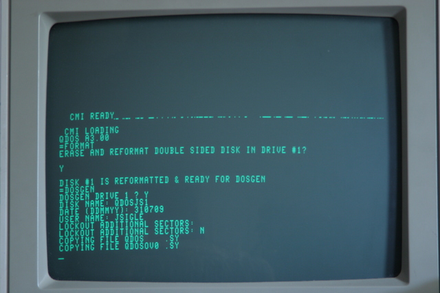
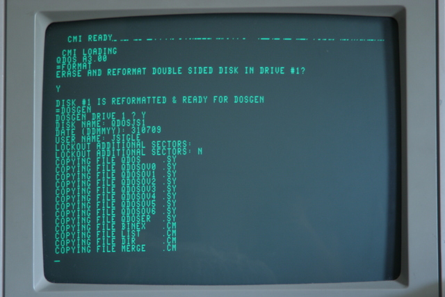
On the other hand, you may also understand the appeal of good system disks, like those I had received from PN :-). I had made two backups of the most recent version before really using it.
This turned out to be a good idea, when I found later that two of the three copies had some way or another become unbootable. No problem so far. But with that experience, I soon sat down, and modded from Single-Sided-flip-over-able to Double-Sided all of my remaining empty 8" disks, to make additional backups of all revisions of the system disks. - "Soon" means: after playing around with the CMI a bit more, trying it out, programming a few sounds from scratch which I liked quite a bit, and after having produced the first of the two musical sketches featured below. And, after being very happy having all that on the very special all my first CMI stuff working disk.
And on DAT, here is the audio:
Well. The CMI / MDOS / QDOS backup utility overwrites a complete disk at once. You may guess where the highly unimportant second backup of the last processed, least important, oldest version system disk accidentally went.
I tried to re-create similar sounds and a similar Page R sequence, as long as I'd still remember bits of the previous work.
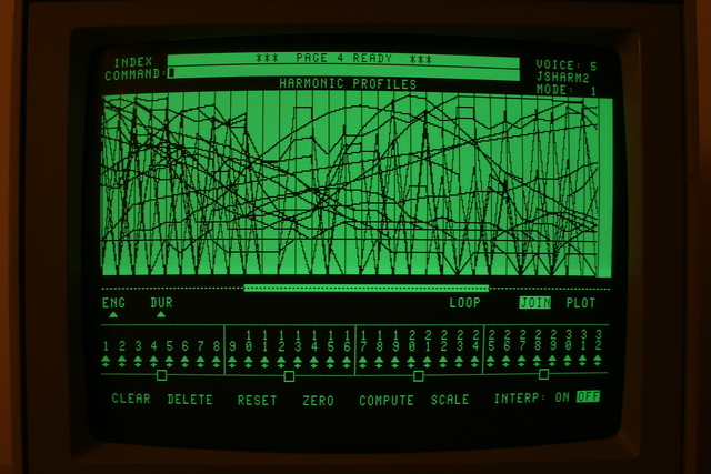
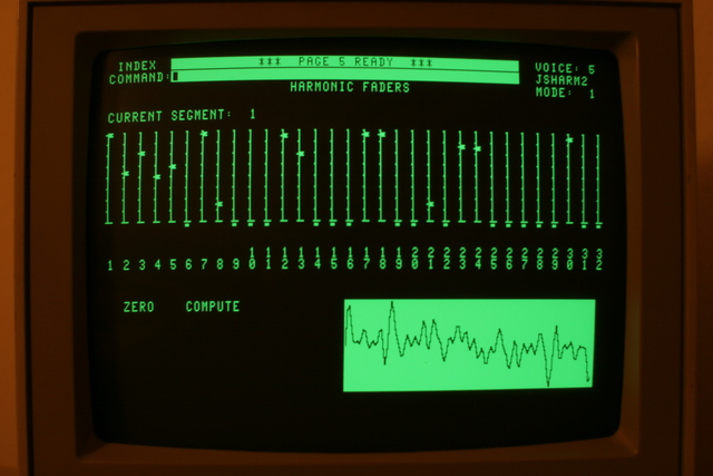
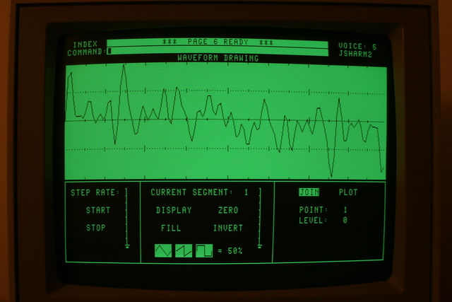
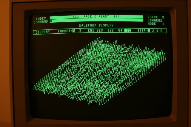
This was slightly non-trivial: The sounds for the interesting background texture pattern in this piece had been made by experimenting with the HARMONIC ENVELOPES, WAVEFORM GENERATION and possibly even WAVEFORM DRAWING features. The result came from multiple frequency profiles varying over time (the "holy" working disk would have contained additional versions of that sound).
The surviving screenshots which I made for cursory documentation, are far too little to recreate the original programming: Page 4 as shown above, covers up to 32 harmonic envelopes - and each curve could mean Energy (ENG) or Duration (DUR)... On Page R, the background texture pattern also used multiple tracks, created by filling a bunch of notes and semi-arbitrarily offsetting some until it sounded fine.
So I only tried to preserve some aspects of the approach of the initial piece. This was possible without spending the time for perfect listening. The images below show the process of layering and modifying harmonic envelopes as photographed during the re-make attempt. - The resulting cover version is different, but bearable at least :-)
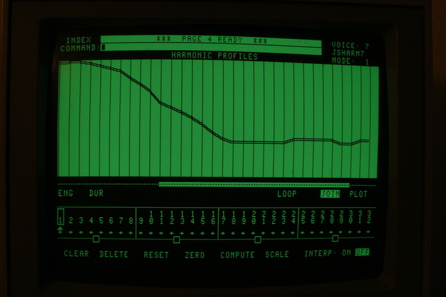


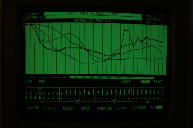
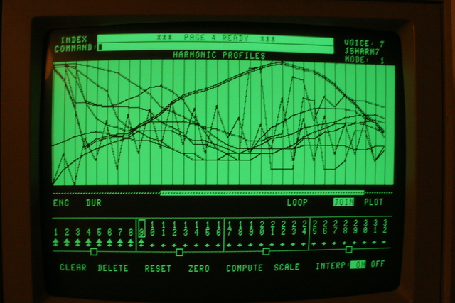

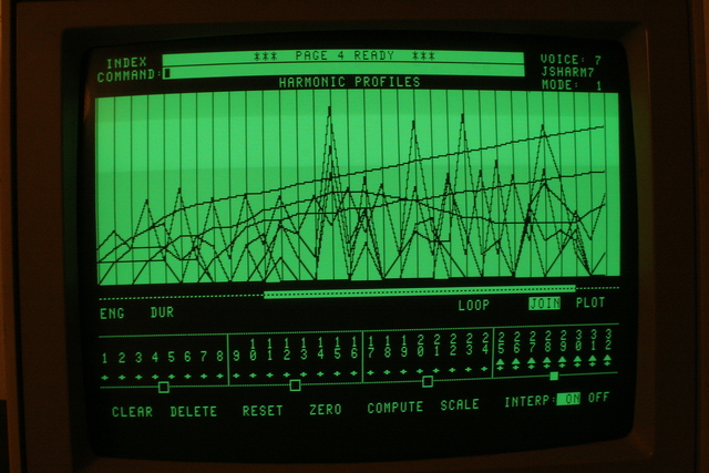
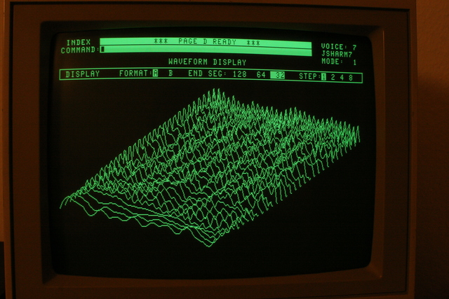
What the examples show very beautifully, and what can be an impressive experience when experimenting with the HARMONIC ENVELOPES editor - is that the CMI II is not just a sampler with filters and a sequencer, but also includes very capable and distinctive features for the synthesis of quite interesting sounds from scratch.
And, that it has a doubtlessly functional user interface - remember, the pieces above were made by an amateur in his first few hours using the system.
Sampling and the metronome click output were still missing. Therefore, my first musical experiments (above) have a distinctively audible tick in one of the tracks. But finally, I traced back both problems to non-standard cabling: "The Conductor" card uses the click and must be hooked into the cable between the CMI-01 master card and the back of the machine. Since I put it back in, the restored CMI has worked like a charm.
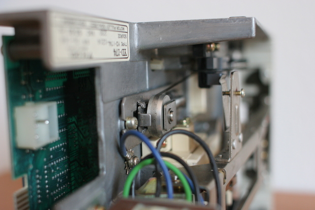
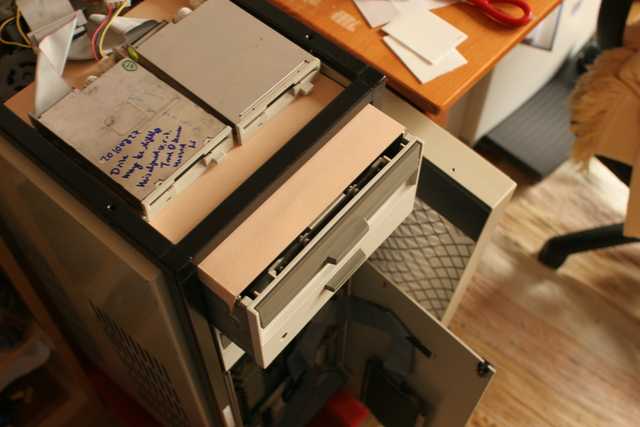
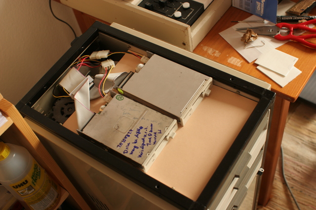
My CMI II has two Ye-data YD-174 full-height 8 inch Double-Sided, Single-Density (DS/SD), soft-sectored floppy drives.
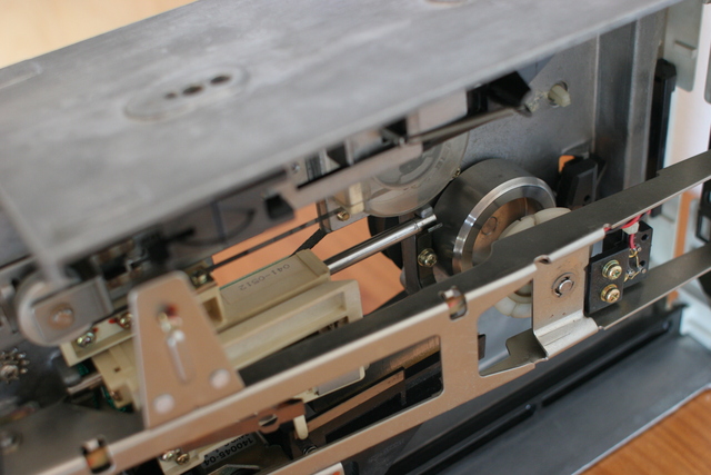

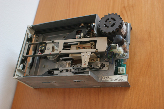
The noise they produce when engaging the heads and scrubbing them across the disk puts a little strain on the Woman-Acceptance-Factor (WAF) of this otherwise so remarkably unobtrusive, tiny white machine.
I find the fact even more unpleasant that the drives have constantly rotating, relatively high powered 110V/220V motors. They add at least as much noise as all the system fans. They also draw a substantial amount of power.
Further, 8" media are relatively rarely offered, usually as single items, and thus about 100x as expensive as 3.5" disks. And finally, none of my other systems has an 8" drive in use, so 8" means a dead end for data exchange.
Consequently, I did some research in floppy drive theory and found out that the conversion might be a straightforward thing, which other users performed quite regularly for other computer systems.
I'm currently writing this report from memory, using only previously made fotos. "IIRC" means "If I remember correctly", and "AFAIK" means "As far as I know". Please don't hesitate to ask if anything is unclear, or to correct me if I write anything wrong.
Below, I'll first show some images from my system; then provide all the detailed background information. Hyperlinks provide many secondary files covering more or less suitable floppy drives, detailed drive jumpering and modding guides, as well as suggested 50-pin <->34-pin adapter pinouts.
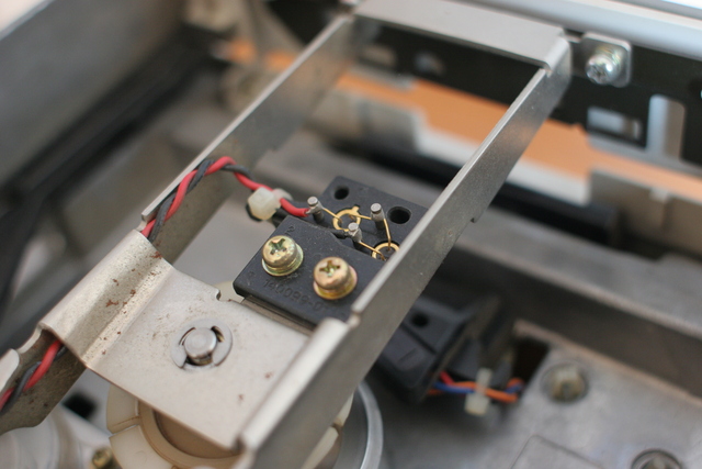
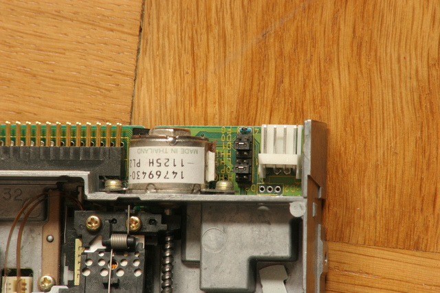
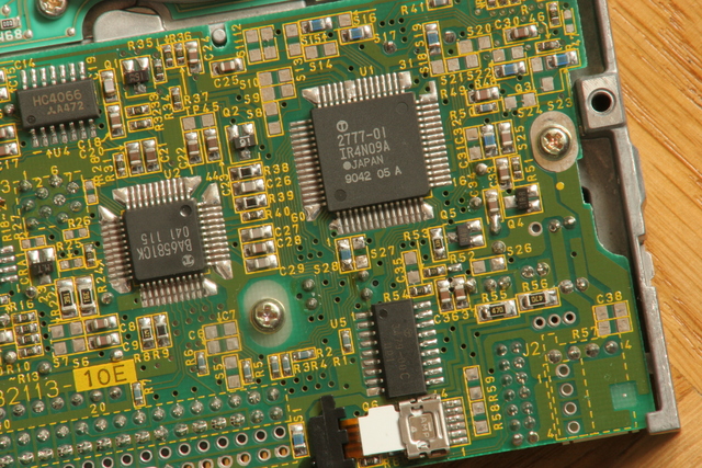
A TEAC HD-235HF 6291-U drive which has only the Drive Select 0 and Drive Select 1 jumpers. This drive required a little modification to supply -ready on pin 34 (and yes, that wire looks rather too strong to look fine, and the soldering iron I used was much too large as well).
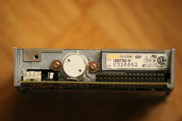

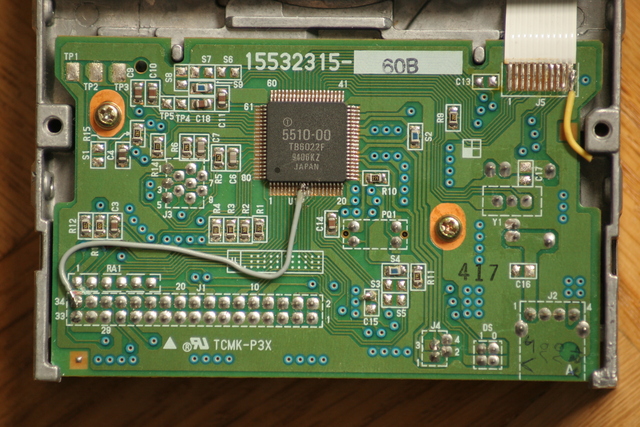
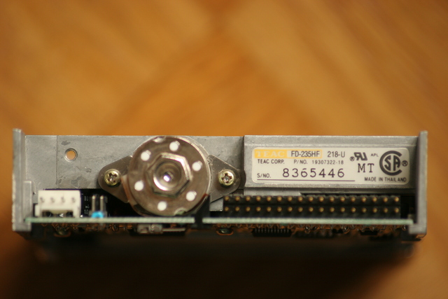
A TEAC HD-235HF 218-U drive which has more jumpers but still needs a little change; please notice the moved SMD bridge at S27/S28 in the middle of the screen (and moreover, the actual drive layout deviates slightly from what is shown in the docs linked below):
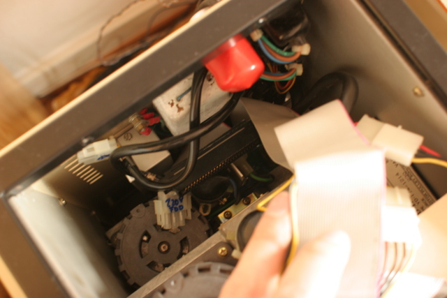
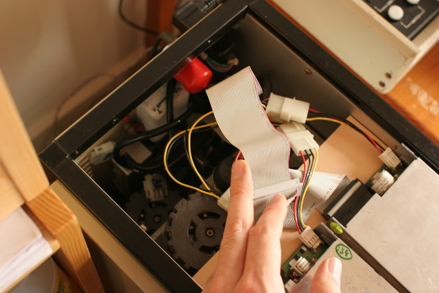
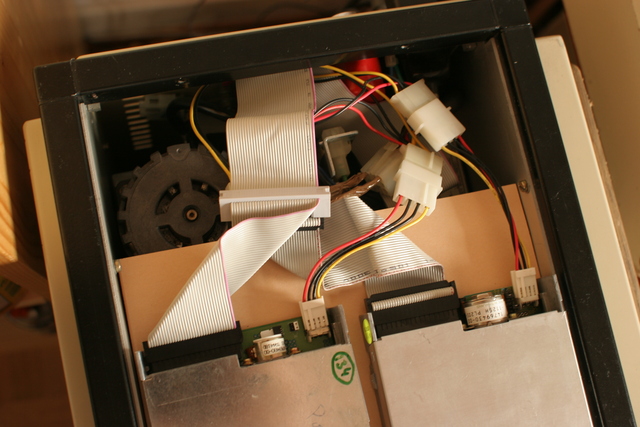
The following image shows a single modded 3.5" drive and one of the original 8" drives both attached to the normal drive cable of the CMI II at the same time. The 50-pin <-> 34-pin floppy interface adapter used here was made by Fairlight (temporarily taken from a CMI III MFX2). Its pinout matches my own research findings. The floppy drive power connector seen here is used by Fairlight in the CMI III as well.
Using the drive select number inversion switch at the QFC-6 controller, I could either boot from the 8" drive and simply use the backup utility from the QDOS / diagnostic disk to transfer disk images onto 3.5" media, or I could boot the so generated system disk from the 3.5" drive. I have copied maybe three to five disks with this setup (just as I didn't have more target disks back then). Anything worked flawlessly, no special preconsiderations required.
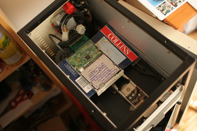
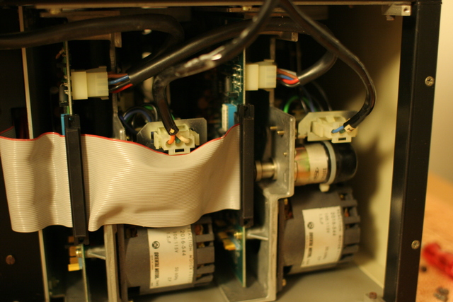
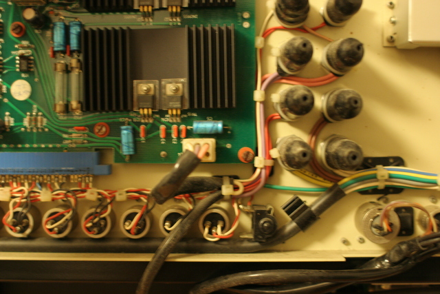
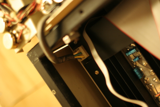
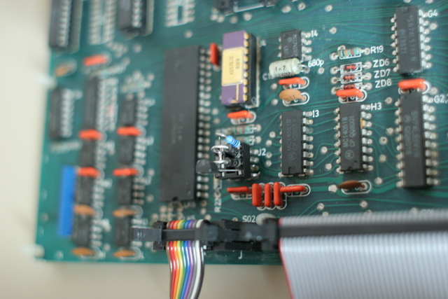
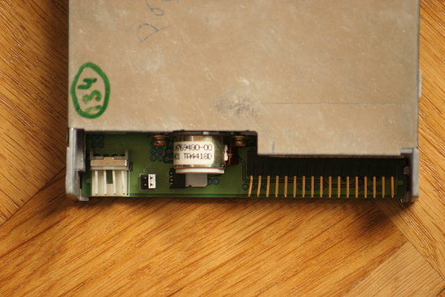
The following images show both TEAC 3.5" drives attached to the QFC-6 via my own cable arrangement. Images sorted from the controller to the drives:
I have not used the system much as I didn't have the time. But what I tried out after doing the floppy mod and transferring the system disk, the diagnostic disk and my work disk, has functioned perfectly so far. The much more quiet (i.e. less noise, less stress and less heat generating) operation is a very favourable result in my opinion.
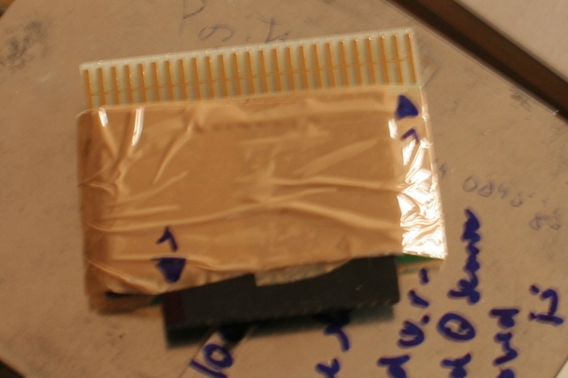
Sorry, for not supplying a detailed photo of either 50-pin <-> 34-pin adapter: I wrapped both the Fairlight cardboard adapter and my self made intra-cable one into the brown adhesive tape for isolation purposes during the experimental stage. Apparently I have not made a detailed photograph of either of them before that, and when everything worked for me, have left both inside their respective machines. (I'm somewhat surprised by the lack of a more useful photo, but I've just re-reviewed what's available right now, also checked for consecutive image names, with no better result.)
I remember however having videotaped some CMI operation with the 3.5" drive - but I'm afraid I wont be able to get out the material and put it here in the really near future.
Below is another glimpse at the cardboard adapter by Fairlight, already wrapped before it went back to the Series III. Please note the triangles indicating pin 1 on the respective connector side; they are at opposite sides for either connector. Rotating the 50-pin connector and the 34-pin connector is what allows for the straight through connection of most wires between them.
The first enlarged image reveals that the all-GND-side of the cardboard adapter is facing up, because all pins on this side of the cardboard adapter are visibly connected by a single line. The second enlarged image is from the photo shown further above, it shows the adapter in place before it has been wrapped, I think it sits in the same orientation and as you can see there are no active parts on the board (nor any pins from parts that might be below, there are only a few vias for the rare lines that need other but straight connections).


A suitable adapter pinout is described in multiple articles linked further below.
I don't want to even create a drawing for you right now, as I'm a bit worn from adding all the other things to this page. And without taking the old and new drives into my hands, to look at their boards and connectors, a small risk remains of getting it the wrong way round. So for now I leave the task up to you (or kindly ask for some patience).
I might however look for my original drawings, and finally open up the boxen and get these two things out again for a photo session :-) after completion of a few competing tasks.
Please note: The CMI IIx has Double-Density (DD) drives whereas the CMI II has Single-Density (SD) drives. Moreover, your CMI IIx may have a more recent disk controller than my CMI II.
This may affect the transferability of the following information to your system (although I would not expect that for reasons given below).
In any case, you're reading and possibly putting to use the following information completely at your own risk. Please only use it if you have sufficient technical understanding, skills, and please review the referenced original technical documentation for yourself.
Specifically, I provide links to Shugart-Bus, and IBM-PC type floppy connector pinouts in the Web, and to a number of articles regarding 8" -> 5.25" or 3.5" drive replacements for other computer sytems, you can consult.
If you're unsure please consider asking a knowledgable person. I might also be able to help, but the time I can give you is hard to predict.
The 8" floppy drives are connected to the CMI II QFC-6 (or CMI IIx / CMI III QFC-9) floppy controller via a standard Shugart-Bus. That uses one plain cable to connect up to for drives to the controller, and its specification...
If you buy a standard 3.5" drive today, however, it will probably follow the IBM-PC standard instead. That uses a cable with a partial twist to connect up to two drives to the controller, and it also differs from the original Shugart-Bus in the following ways:
All other signals have been left compatible between the original Shugart-Bus and the IBM-PC floppy drive specification, but those which IBM changed are sufficient to make a drive configured for an IBM-PC not work with a computer that provides a standard Shugart-Bus.
Finally, the total number of pins has changed from 50 to 34, but if you study the detailed layout, you may discover that the connector pinout has also been rotated. Consequently, an adaptor can employ straight, non-crossing connections between most corresponding pins of the 50-pin Shugart-Bus and the 34-pin IBM-PC connector.
Suppliers of floppy drives can design these with or without jumpers that can be used to configure any of the above parameters to be either IBM-PC-compatible, or Shugart-Bus-compatible.
As the PC dominates the market today, many drives come without jumpers, configured for PC-use and for nothing else. Some may still be configurable by cutting PCB traces, or modifiable by rewiring some pins from their interface to different pins in the built in controller ICs.
The CMI will definitely need the -ready signal from the drive. The CMI will not use a drive that does not supply this signal.
Both the Ensoniq Mirage Sampler and the Commodore Amiga are other computers who want to see -ready from their drives. The Amiga community has supplied both extensive lists of drives which supply the -ready signal, and even detailed guides with fotos showing how to mod other drives.
Please note, that I'm currently unsure whether the Amiga would really require a High-Density (HD) drive - I'd naively recommend to prefer a HD drive (and if that shouldn't work, a Triple-Density drive) for a CMI II / CMI IIx / CMI III mod, because of the support for the higher rotational speed, and because of the need to store substantially more than 1 MB on a single disk (8" DD and 3.5" HD capacities are similar). For the Amiga, the HD drive does, and for the CMI it might be able to work with both DD and HD 3.5" media, but after all HD is just much more easily available by now.
Please also note, that writing a medium with a 3.5" or 5.25" DD drive first, and with a HD drive thereafter, and then trying to read it on a DD drive will probably render unsatisfactory results. HD drives have smaller read/write heads - so a HD drive can perfectly write (and read again) its fine track only in the middle of a pre-existing wide DD track - but the wide DD head would be unable to separate the two and only get confused.
And another note: the rotational speeds of 3.5" drives and CMI II 8" drives might be slightly different. This has turned out to be unproblematic in practice (If I remember it correctly, it will only have the effect that the CMI II doesn't use all the magnetic storage space theoretically available in each track circle on a 3.5" disk). I don't know (for sure) whether the rotational speeds of the CMI II and CMI IIx drive are the same, or whether you will run into problems with a CMI IIx in this respect - but you can just try it out. (I must really look at my hardware again to find out whether I did anything to change drive rotational speed because I see I wrote a related note onto one of the TEAC drives; that will require at least a few days.)
The same thing applies to the recording density used by the disk controller. IIRC, the CMI IIx may format a first track in SD to retain some readability on the CMI II, and all others in DD. A HD 3.5" floppy drive might however be able to support both formats (CMI IIx data density does not exceed the possibilities offered by PCs, especially beyond standard-PC formatting). If a HD drive should not work, there are Triple-Density drives available to try. (I'm perfectly uneducated on how much the drive needs to know about the various data encoding formats; but I guess that when a sufficiently high frequency response range is available in the drive, the rest is just the controller's business).
Many drive recommendations, including jumperable or moddable drives, detailed photo guides, and links to secondary extensive collections for a large variety of drive types:
I often ended up with some TEAC FD-235xx xxx-x High-Density drive (e.g. the FD-235HF A700 mentioned above), maybe because they often have jumpers or accessible signals for modding, or because they were the ones that survived my usage and/or storage conditions at all.
Cave: There are numerous variants of this drive family, and they differ by the final numbers in the type designation. So you may get an FD-235HF xxx-x that has all possible jumpers, and another one named FD-235HF xxx-y, that has none or just the ones for the drive select lines. Look here to get a feeling (and ask your ebay seller for exact details):
I've successfully used some TEAC FD-235 drive (with jumpers or self-modded) years ago to replace the drive in an Ensoniq Mirage II, and two of them (maybe both modded) for the CMI II just recently (after having used a modded Alps first, which I replaced later on).
If you should be going to mod a TEAC drive, be warned not to losen the screw(s) that fix(es) the main PCB! The track 0 alignment may thereby be lost and ... well, I did it and it doesn't really speed up one's progress. (One of the notes on the left drive in the pictures above reminds me that it might still be less than perfectly aligned.)
As a sidenote, I recently found the CMI III to also have a (IIRC) TEAC FD-235HG xxx-x drive built in, operated from a QFC-9 controller, possibly with updated ROM. That drive happens to have all possible jumpers, including one to get -ready on pin 34, but I didn't want to canibalize it for the CMI II :-)
Depending on what you want to do, you can e.g. make a cardboard adapter that plugs in between the original CMI floppy cable and a single 3.5" drive, or an intra-cable-adapter that allows you to connect a ribbon cable to the controller on one end, and to two floppy drives on the other end. Both options have been shown in photos above, and even more exist.
Required connections
The following documents provide further information (from other computer worlds), including connector pinouts. I designed mine from scratch and all by myself (in order to avoid trouble from using something similarly looking that should still not be applicable for the CMI). But IIRC, regarding the connections to be made, I came to an at least highly similar solution to what these sources suggest, and identical to the adapter Fairlight provides for the CMI III.
The CMI II 8" drives have a 50-pin cardboard connector. The CMI II floppy controller has a 50-pin, dual row, male, board mounted header plug connector that accepts a ribbon cable with a 50-pin, female, IDC line socket connector. The CMI floppy drive cable routes the 50-pins from the controller straight to both drives.
A 5.25" drive usually has a 34-pin cardboard connector, and a 3.5" drive has a 34-pin dual row, male, board mounted header plug connector. An IBM-PC type floppy controller cable would twist the drive select pins between two (+-groups) of its floppy drive connectors, and would therefore either need IBM-PC like drive select jumperint on the floppy drives, or, if you were to make an adaptor from the 50-pin controller to a 34-pin cable, you would have to use a 34-pin connector cable with connectors for both floppy drives, and no twist between them.
5.25" type 34-pin cardboard to 3.5" type dual row female socket plug adaptors, that are placed onto a 3.5" to connect it afterwards with a 5.25" controller cable, are readily available from the PC business.
To make an adaptor for a single 3.5" drive to the original CMI floppy cable cardboard connector, you might use a suitably made PCB with a cardboard connector on one side, and a female 34-pin connector to plug into the floppy drive. The 34-pin connector can be soldered directly onto the PCB, and this is what Fairlight provides for the CMI III.
Most pins can be routed straight from the cardboard-connector contact to a corresponding 34-pin-connector pin, no crossings nor shifts are required. Only a few lines need to be cut, and/or individually routed. Because of this, the cardboard portion can even be made from "Streifenraster" (maybe "prototype" or "breadboard"?, see below) printed circuit board with straight, parallel lines of copper.
This adaptor could be used to replace one 8" drive, or both, or even to add up to two 3.5" or 5.25" drives to an existing setup (with a suitable cable and maybe in combination with a manual drive select switch, I have not tried that).
The replacement of a single drive out of two would be required for an initial copying of the operating system and your working disks.
To directly connect two 3.5" floppy drives to the CMI QFC-6 (or maybe QFC-9) floppy drive controller, I actually made an adaptor with 50-pin IDC male on one side, 34-pin IDC male on the other side, and "Streifenraster" (maybe "prototype" or "breadboard"?, see below) printed circuit board with single sided straight parallel connections in between, most of which were left untouched.
I used a normal 50-pin internal SCSI ribbon cable from the controller to that adaptor, and similar, 34-pin ribbon cable without any twist to connect the distant side of my adaptor to both floppy drives.
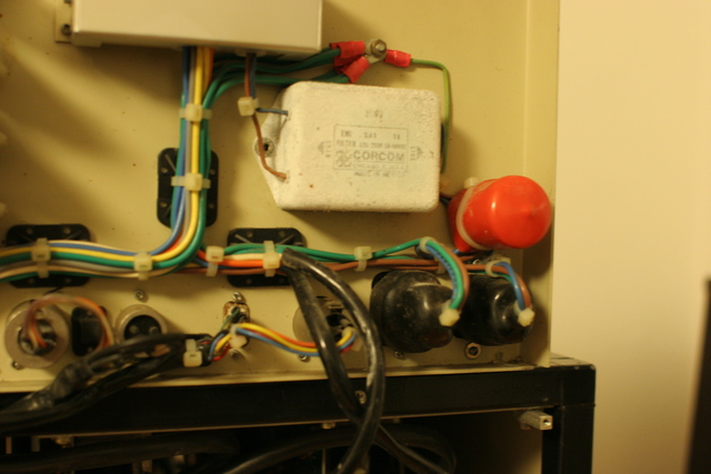
The Fairlight CMI has two power supply connectors for its 8" drives. Caution: 115V or 230V will be available on these connectors! Do not work here if you don't know for sure what you're doing! You can either remove the individual plugs from a standard PC adapter (they are usually held in place in their plastic plug by a fluke/barbed hook coming as small metal piece from each pin and can be pulled back in the direction of the cable when this is released) and use them to contact the individual pins (only 0V, +12V and +5V, but not 115V or 230V!) in the Fairlight power supply connector.
In my CMI III, however, and also among its replacement parts, I found a suitable cable matching the Fairlight power supply connector on one side, and a 3.5" floppy drive power connector on the other side (shown in a photo above). So the required parts are certainly available (Radio Shack?, Reichelt, Conrad Electronic etc.)
Not really required - the traditional method for home-made PCBs:
Some guys have reported that it is possible to print a board layout with a laser printer, and hot-iron it (or transfer it with a laminating machine) directly onto PCB material. The fact that this simplified approach works is especially disturbing :-) for guys like myself who used nothing less than a laser printer from the beginning to make the transparencies for UV exposure etc. many many years ago...
You can also have your cardboard adaptor PCB professionally made. Nowadays, many sources offer such a service accepting plot-data or even offering on-line tools for board design. Ask your favourite search engine, please, but for one or two floppy adaptors that may be overkill.
As the adapter is very simple you can also start with what is called Streifenrasterplatine in Germany (more links below), single sided (or double sided, suitable thickness, if you want to plug into the Fairlight 50-pin floppy cable), with all straight through links from one side to another. Only a few of the signals need to be cut/isolated and/or rerouted. Both 34-pin and 50-pin IDC connectors can be added on either site as required.
And finally, you can just cut a floppy cable in half and connect the open wire ends to a 50-pin connector (type as required) to go either into your controller, or into the existing floppy cable.
However, I think that direct, multiple pin, soldered ribbon cable connections, especially where the connector and the ribbon cable wires are not aligned as 1:1, have a high risk of wires getting lose and producing chaos. So I'd recommend a solution that uses no cables but PCB connections between the 50-pin and 34-pin adapter ends.
50-pin ribbon cables are available as normal SCSI or FAST SCSI cables for internal drives from older PC or other computer technology applications. 34-pin ribbon cables without a twist may be available from the AMIGA or maybe other non-PC-type computer part market. I got a large box with all types of surplus SCSI, Floppy, IDE etc. cables on ebay for next to nothing.
Don't forget that you need to thoroughly isolate your product so that the foreseeable rather than accidental contact with other parts of the machine will not cause immediate destruction.
Clicking on any of the following links should open a new browser window. If the new window obscures your view to this page, you can close it, or resize it, or move it to the side.
General links:
The Sydney Powerhouse Museum has an online database with several related and very interesting exhibits:
 This Web page was prepared by myself,
and so were all included graphic elements.
© 2009-2010 Dr. med. Jörg M. Sigle, Kunstvolle EDV & Elektronik